
Uncover the working principle of diaphragm compressors and common troubleshooting tips
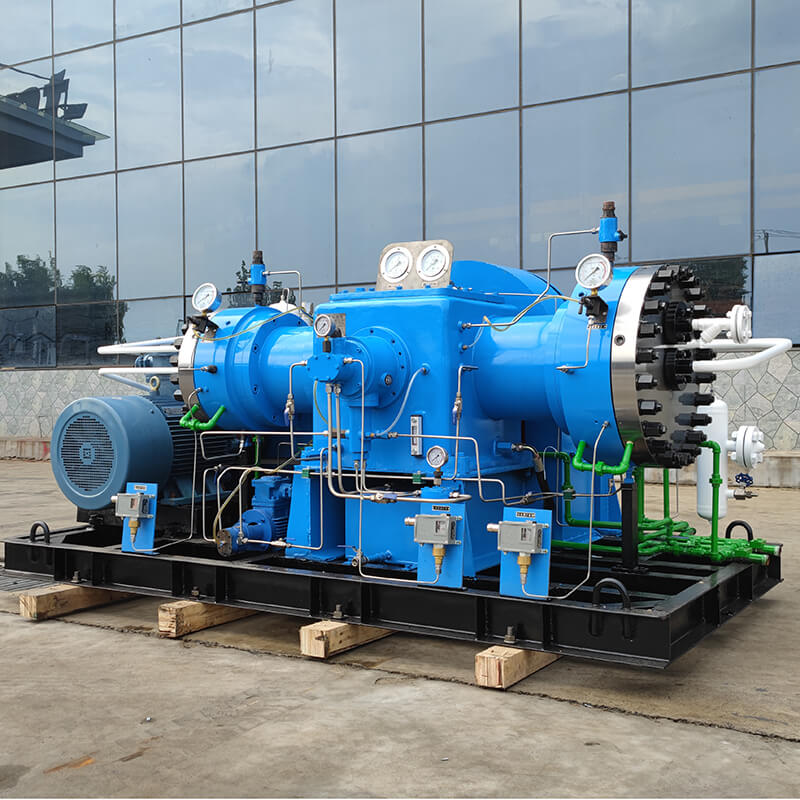
In modern industrial production, diaphragm compressors play a vital role in situations where gas purity, sealing and safety are extremely high. With its unique characteristics of oil-free compression, zero leakage and no pollution to the medium, it is widely used in high-tech fields such as chemical industry, medicine, food, semiconductor, nuclear industry, aerospace, etc. Whether it is compressing high-purity gases such as hydrogen, oxygen, and nitrogen, or handling flammable, explosive, toxic, and corrosive gases, diaphragm compressors have shown their incomparable advantages. This article will deeply analyze the working principle of diaphragm compressors, elaborate on its common types of failures and causes, and provide practical maintenance suggestions and fault prevention measures, aiming to help readers fully understand and effectively manage diaphragm compressors to ensure their long-term stable, efficient and safe operation.
Working Principle of Diaphragm Compressors
The core principle of diaphragm compressors is to achieve gas suction, compression and discharge through the reciprocating motion of a flexible diaphragm. Unlike traditional piston compressors, the diaphragm acts as a physical barrier between the gas and the crank-connecting rod mechanism (or hydraulic oil), completely eliminating oil contamination and gas leakage during the compression process, thereby ensuring the high purity of the output gas.
Core structure analysis
Diaphragm: This is the most critical component of the diaphragm compressor, usually made of high-strength, corrosion-resistant, and fatigue-resistant flexible materials, such as multi-layer stainless steel, polytetrafluoroethylene (PTFE) or composite materials. The diaphragm divides the compression chamber into two parts: one side is in contact with the gas to be compressed, and the other side is in contact with the hydraulic oil or mechanical transmission parts (such as mechanical diaphragm type). Its main function is to provide a closed space during the compression process and prevent particles generated by lubricants or mechanical parts wear from entering the compressed gas.
Hydraulic system or mechanical transmission mechanism:
Hydraulic diaphragm type: This is the most common type at present. A built-in hydraulic oil pump delivers hydraulic oil to the back of the diaphragm, and the diaphragm is deformed by the pressure change of the hydraulic oil, thereby achieving gas suction and compression. The hydraulic system usually also includes hydraulic cylinders, pistons, safety valves, oil tanks and cooling devices. The cleanliness, temperature and pressure of the hydraulic oil are critical to the performance of the compressor.
Mechanical diaphragm type: relatively rare, the diaphragm is directly driven to reciprocate by a mechanical connecting rod. This structure is usually suitable for lower pressures or special applications.
Crank connecting rod mechanism: converts the rotary motion of the motor into the reciprocating linear motion of the hydraulic piston (or mechanical diaphragm), thereby driving the diaphragm.
Inlet valve and exhaust valve: located on both sides of the compression chamber, both are one-way valves. The intake valve opens during suction to allow gas to enter; the exhaust valve opens when compression is completed to allow compressed gas to be discharged. These valves usually use high-quality valve plates and valve seats to ensure efficient sealing and reliable one-way flow.
Valve box: The cavity that accommodates the intake valve and exhaust valve is exquisitely designed to optimize the gas flow path.
Detailed explanation of working cycle
The working cycle of diaphragm compressor is usually divided into three stages: suction, compression and exhaust. It is similar to reciprocating compressor, but it is realized through diaphragm:
Suction stroke: The motor drives the crank connecting rod mechanism to make the hydraulic piston (or mechanical diaphragm) move backward. At this time, the diaphragm forms a negative pressure area on the outside (gas chamber). When the pressure in the gas chamber is lower than the gas pressure in the intake pipe, the intake valve automatically opens under the action of pressure difference, and the compressed gas is sucked into the gas chamber. The exhaust valve remains closed due to the decrease in pressure in the gas chamber.
Compression stroke: The hydraulic piston (or mechanical diaphragm) starts to move forward, pushing the diaphragm to bulge toward the gas chamber. The volume of the gas chamber gradually decreases, the internal gas is compressed, and the pressure increases accordingly. During the entire compression process, the intake valve is closed due to the increase in pressure in the gas chamber to prevent gas backflow.
Exhaust stroke: When the pressure in the gas chamber rises to exceed the pressure in the exhaust pipe, the exhaust valve automatically opens under the action of pressure difference. At this time, the compressed gas is pushed forward further by the diaphragm and discharged from the compressor through the exhaust valve. Once the diaphragm reaches the end of the stroke, the exhaust stroke ends and the compressor enters the next suction cycle.
Purity guarantee mechanism
The key to the diaphragm compressor’s ability to ensure pure and pollution-free gas lies in the complete isolation of the diaphragm. The diaphragm completely separates the moving parts (such as pistons, connecting rods, hydraulic oil, etc.) from the compressed gas. This means:
No oil pollution: Hydraulic oil or mechanical lubricating oil will not come into contact with the compressed gas, completely avoiding the impact of oil vapor or oil droplets on gas purity. This is crucial for industries such as food, medicine, and semiconductors.
Zero leakage: High-quality diaphragms and precise sealing structures ensure that the gas will not leak into the external environment during the compression process, and conversely, external air or impurities will not enter the gas cavity. This is of decisive significance for compressing toxic, flammable, explosive or precious gases.
No wear particles: The flexible movement of the diaphragm avoids direct friction between metal parts, so that no wear particles are generated to contaminate the compressed gas.
Common faults and causes of diaphragm compressors
Although diaphragm compressors are known for their high reliability, various faults may still occur during long-term operation. Understanding the types of these faults and their underlying causes is the basis for effective diagnosis and elimination.
Diaphragm damage/rupture
Phenomenon: The compressor pressure cannot be established, the exhaust volume drops significantly, hydraulic oil appears in the gas (hydraulic diaphragm type), and the compressor vibrates or makes abnormal noise.
Cause analysis:
Fatigue wear: The diaphragm will produce material fatigue in long-term high-frequency reciprocating motion, eventually leading to cracks or ruptures, especially at the end of its service life.
Overpressure operation: The working pressure of the compressor exceeds the designed pressure bearing capacity of the diaphragm, resulting in instantaneous or long-term overload.
Medium corrosion: The compressed gas is corrosive to the diaphragm material, resulting in a decrease in the performance of the diaphragm material or local perforation.
Improper installation: The diaphragm is not centered during installation, the tightening bolts are not torqued evenly, and the pre-tightening force is insufficient or excessive, which may cause uneven force on the diaphragm and accelerate damage.
Foreign body impact: Solid particles contained in the gas impact the diaphragm surface at high speed, causing physical damage.
Hydraulic system abnormality: Hydraulic shock caused by air in the hydraulic oil, or excessive fluctuations in the hydraulic oil pressure, will bring additional stress to the diaphragm.
Valve failure (intake valve/exhaust valve)
Phenomenon: Insufficient exhaust volume of the compressor, large pressure fluctuations, reduced compression efficiency, abnormal knocking sound of the compressor (valve broken or stuck).
Cause analysis:
Wear and fatigue: The valve plate will continue to wear during high-speed and high-frequency opening and closing, especially in the part in contact with the valve seat. Long-term work will cause the valve plate material to fatigue, lose elasticity or break.
Foreign body stuck: Dust, particles or moisture contained in the compressed gas are stuck between the valve plate and the valve seat, causing the valve to be unable to close or open completely.
Spring failure: The valve plate spring (if equipped) is fatigued, deformed or broken, causing the valve plate to react slowly or fail to return to its position normally.
Valve seat damage: The valve seat surface is corroded, worn or deformed, resulting in poor sealing of the valve plate.
Over-temperature operation: High-temperature gas may cause the performance of the valve material to deteriorate or deform.
Abnormal oil pressure (for hydraulic diaphragm type)
Phenomenon: The compressor pressure cannot be established or is unstable, the diaphragm movement is abnormal, the hydraulic oil temperature is too high, and the safety valve frequently releases pressure.
Cause analysis:
Insufficient or deteriorated hydraulic oil: Insufficient hydraulic oil causes the pump to suck empty, or the hydraulic oil deteriorates, oxidizes, and changes in viscosity after long-term use, affecting the normal operation of the hydraulic system.
Hydraulic oil contamination: Water, air or solid particles are mixed in the hydraulic oil, causing oil circuit blockage, pump wear, and valve jam.
Hydraulic pump failure: The hydraulic pump is worn, leaks internally, the efficiency is reduced, or the drive motor fails, and it cannot provide sufficient hydraulic power.
Oil circuit blockage: The filter is blocked, the pipeline is bent or deformed, resulting in poor oil flow.
Safety valve failure: The safety valve setting pressure is inaccurate, stuck or damaged, and it cannot be opened or closed normally at the specified pressure.
Cooling system failure: The hydraulic oil cooler is blocked, the fan fails, or the cooling water is insufficient, resulting in excessive oil temperature and reduced oil viscosity.
Motor failure
Phenomenon: The compressor cannot start, it is difficult to start, the motor makes abnormal noise during operation, the motor heats up seriously, and the circuit breaker trips.
Cause analysis:
Power supply problem: unstable power supply voltage, phase loss, undervoltage or overvoltage.
Overload: The compressor is overloaded for a long time, resulting in excessive motor current.
Bearing damage: The motor bearing is worn, lacks oil or is improperly installed, causing increased friction, noise and heat.
Winding failure: The motor winding is short-circuited, open-circuited or the insulation is aged.
Poor heat dissipation: The motor fan is damaged, the heat dissipation holes are blocked or the ambient temperature is too high.
Seal leakage
Phenomenon: Gas leakage (smell, pressure drop), hydraulic oil leakage (visible).
Cause analysis:
Aging of seals: After long-term use, the materials of seals, O-rings, gaskets, etc. age, lose elasticity or harden.
Improper installation: The seals are damaged, misaligned, insufficient or excessive tightening force during installation.
Surface roughness does not meet the standard: The machining accuracy of the mating surface is insufficient or there are scratches.
Excessive vibration: abnormal vibration of the compressor causes loose connections or damaged seals.
Medium corrosion: the sealing material is incompatible with the fluid medium, resulting in corrosion and failure of the seal.
Abnormal vibration and noise
Phenomenon: severe vibration, harsh friction, knocking or roaring sounds occur during the operation of the compressor.
Cause analysis:
Loose anchor bolts: the compressor base is not firmly fixed to the ground, resulting in overall vibration.
Unbalanced components: rotating components (such as motor rotors and connecting rods) have dynamic balance problems.
Bearing damage: motor bearings, crankshaft bearings, connecting rod bearings, etc. are worn or poorly lubricated.
Valve problems: broken valve plates and spring failures cause uncoordinated valve movements and knocking sounds.
Pipeline resonance: the design of the intake and exhaust pipelines is unreasonable, resonating with the natural frequency of the compressor.
Hydraulic shock: the hydraulic system is unstable, such as air in the hydraulic oil and large oil pressure fluctuations.
Loose parts: fasteners such as bolts and nuts are loose.
Maintenance and care recommendations for diaphragm compressors
Effective maintenance is the key to ensuring long-term and reliable operation of diaphragm compressors. Following the following recommendations can significantly extend the life of the equipment and reduce the occurrence of failures.
Regular inspection and monitoring
Daily inspection: Check whether the sound and vibration of the compressor are normal; observe whether there is gas or hydraulic oil leakage at each connection; check whether the pressure gauge and thermometer readings are within the normal range; check the hydraulic oil level.
Weekly inspection: Clean the dust on the surface of the equipment to ensure good heat dissipation; check whether the electrical connectors are tight; check whether all fastening bolts are loose.
Monthly inspection: Check the color, transparency and smell of the hydraulic oil to determine whether it needs to be replaced; check the operation of the cooling system (fan, cooler).
Operation record: Establish a detailed operation log to record each startup and shutdown time, operating pressure, temperature, current, maintenance content and failure occurrence.
Lubrication system maintenance (for hydraulic diaphragm type)
Hydraulic oil quality management:
Regular replacement: Replace the hydraulic oil strictly according to the manufacturer’s recommended cycle, usually 1000-2000 hours or once a year, depending on the operating conditions and oil quality.
Oil selection: Be sure to use hydraulic oil of the model and grade specified by the manufacturer. Mixing different oils may cause performance degradation.
Pollution control: Ensure that the storage environment of the hydraulic oil is clean and use a special filter when refueling.
Oil filter cleaning and replacement: Regularly check and clean the hydraulic oil filter. If it is blocked or damaged, it should be replaced in time to prevent impurities from entering the hydraulic system.
Cooling system maintenance: Regularly clean the hydraulic oil cooler (air cooling or water cooling) to ensure heat dissipation efficiency and prevent the oil temperature from being too high. Check the cooling water flow rate (water cooling).
Valve plate and valve seat maintenance
Regular inspection: According to the operating time or manufacturer’s recommendations, regularly disassemble the valve box to check the wear, corrosion, cracks and deformation of the valve plate and valve seat.
Cleaning and replacement: Clean the deposits or foreign matter on the surface of the valve disc and valve seat. For worn or damaged valve discs, valve seats and springs, original spare parts should be replaced in time to ensure the sealing and flexibility of the valve.
Installation specifications: When replacing the valve disc, strictly follow the installation instructions to ensure the correct direction and uniform tightening force.
Diaphragm inspection and replacement
Regular inspection: After overhaul or reaching a certain operating time, the machine should be disassembled to check whether there are cracks, bubbles, deformation, perforations or local thinning on the surface of the diaphragm.
Preventive replacement: Even if there is no obvious damage, preventive replacement should be carried out according to the manufacturer’s recommended service life (usually 3000-8000 hours, or once every few years, depending on the diaphragm material and working conditions) to avoid sudden failures.
Installation precautions: When replacing the diaphragm, the cleanliness of the diaphragm must be ensured to avoid scratches or contamination during installation. The bolt tightening torque must be strictly in accordance with the instructions to ensure uniform force.
Fastener inspection and tightening
Periodic inspection: Regularly check the tightness of all connecting bolts and nuts of the compressor, including motors, pumps, valve boxes, bases and other parts.
Torque management: For bolts in key parts, use a torque wrench to tighten according to the specified torque to prevent over-tightening or over-loosening.
Cleaning and anti-corrosion
External cleaning: Regularly clean the outside of the compressor to remove dust and oil, keep the equipment clean, and facilitate heat dissipation and inspection.
Anti-corrosion treatment: For compressors working in humid or corrosive environments, regular inspections and anti-corrosion treatments should be performed, such as applying anti-corrosion paint.
Diaphragm compressor failure prevention measures
Prevention is better than cure. By implementing a series of effective preventive measures, the probability of diaphragm compressor failure can be minimized and its service life can be extended.
Strict equipment selection
Matching working conditions: When purchasing a diaphragm compressor, it is necessary to accurately calculate and select the model and material that meet the requirements based on the actual application of gas type, pressure (inlet and outlet), flow, temperature, purity requirements, environmental conditions and other parameters. Avoid the situation of “big horse pulling small cart” or “small horse pulling big cart”.
Professional consultation: Consult professional equipment suppliers or engineers to obtain professional selection suggestions.
Material compatibility: Ensure that the materials of diaphragms, valve plates, seals and parts in contact with gas are well compatible with the gas to be compressed to prevent corrosion or chemical reactions.
Standard installation and commissioning
Solid foundation: The compressor should be installed on a flat, solid foundation with sufficient load-bearing capacity, and take shock-absorbing measures to reduce the impact of operating vibration on the equipment.
Pipeline design: The intake and exhaust pipes should be reasonably designed to avoid excessive length and excessive elbows to reduce pressure loss. The pipeline should have independent support to avoid transferring stress to the compressor body. Flexible joints should be used for pipeline connections to absorb vibration.
Electrical connection: Ensure that the power supply voltage is stable and meets the requirements, the electrical wiring is standardized, firm and reliable, and has perfect grounding protection.
Initial startup inspection: Before the first startup, strictly follow the manufacturer’s instructions to perform various inspections, such as hydraulic oil filling, pipeline cleaning, fastener inspection, electrical interlock test, etc.
Strict operating procedures
Personnel training: All operators must undergo professional training and fully understand the working principle, performance characteristics, operating procedures, emergency treatment methods and safety precautions of diaphragm compressors.
Start-up and shutdown procedures: Strictly follow the startup and shutdown procedures provided by the equipment manufacturer, especially for hydraulic diaphragm compressors. It is necessary to ensure that the hydraulic system is stable before gas compression. Avoid frequent start and stop to reduce the impact on the equipment.
Operation monitoring: Real-time monitoring of various operating parameters of the compressor, including inlet and outlet pressure, temperature, hydraulic oil pressure, motor current, vibration value, etc., and immediately stop and check if abnormalities are found.
Strengthen daily inspections and regular maintenance
Establish an inspection system: Develop a detailed daily inspection plan and inspection list, and strictly implement it, so as to “see, listen, touch, and smell” to promptly detect abnormal signs of equipment.
Develop a maintenance plan: According to the equipment operation time, environmental conditions and manufacturer’s recommendations, develop and strictly implement a regular maintenance plan, including minor repairs, medium repairs, major repairs, etc., for preventive replacement and calibration.
Spare parts management
Reasonable reserve: According to the importance of the equipment, the consumption cycle and procurement cycle of the wearing parts, the common wearing parts and key spare parts such as diaphragms, valves, seals, filters, etc. should be reasonably reserved to deal with sudden failures and shorten downtime.
Spare parts quality: When purchasing spare parts, be sure to choose original or certified high-quality substitutes to avoid using inferior spare parts to damage the equipment.
Media purification
Pretreatment: For gases containing impurities (such as dust, moisture, oil mist), pretreatment equipment such as high-efficiency filters, dryers or deoilers must be installed before entering the diaphragm compressor to ensure that the gas entering the compressor is clean and dry, thereby effectively protecting the diaphragm and valves and extending the life of the equipment.
Conclusion
As an ideal choice for high-purity gas compression, the diaphragm compressor has an irreplaceable position in many key industrial fields due to its unique oil-free and zero-leakage characteristics. In-depth understanding of its precise working principle, identification and elimination of common faults, implementation of scientific maintenance and comprehensive preventive measures are the cornerstones to ensure the safe, efficient and stable operation of diaphragm compressors. Through the detailed explanation of this article, we hope to help users and technicians better manage and apply diaphragm compressors, maximize their performance advantages, and contribute to the sustainable development of industrial production. In future use and maintenance, continuous learning, accumulation of experience, and strict compliance with equipment operating specifications will be the fundamental way to ensure the long-term and stable operation of diaphragm compressors.
Request a Quick Quote Now

Shanghai Sollant Energy Saving Technology Co., Ltd.
Drawing on our years of experience and expertise in air separation and PSA technologies, we deliver customized solutions tailored to your specific needs.