
How to maintain a CO2 compressor? 6 tips to extend the life of the equipment
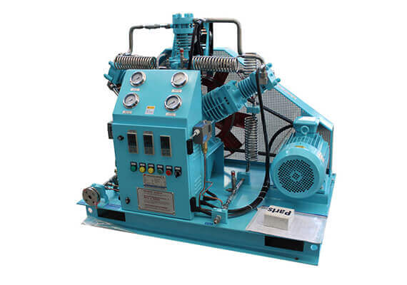
As an indispensable core equipment in modern industrial processes, CO2 compressors have a wide range of applications. From carbonated beverages and beer brewing that we are exposed to in daily life, to urea synthesis and methanol manufacturing in industrial production, to carbon capture and storage (CCS) in the field of environmental protection, as well as low-temperature refrigeration, food quick freezing, medical equipment disinfection, etc., CO2 compressors are everywhere. Its core function is to convert low-pressure CO2 gas into high-pressure gas to meet different process requirements.
However, the working environment of CO2 compressors is very complex: it not only has to withstand high pressure, but also has to deal with low temperature, as well as the micro-corrosiveness and condensability of CO2 itself. These special working conditions place extremely high demands on the materials, structural design and operational stability of the equipment. Once the compressor fails, it will cause production interruption, reduced efficiency, increased energy consumption, and even cause safety accidents and huge economic losses. Therefore, scientific, systematic and continuous maintenance of CO2 compressors is not only a necessary measure to ensure production continuity, but also a cornerstone to extend the service life of equipment, improve return on investment, and ensure the safety of operators. This article will comprehensively and deeply analyze the six core strategies for CO2 compressor maintenance, aiming to provide a detailed and practical maintenance guide for industrial users.
Regularly check and replace the lubricating oil of the CO2 compressor
Lubricants are to CO2 compressors what blood is to a living organism. It builds a thin and tough oil film between the high-speed metal parts of the equipment, effectively isolating direct friction, thereby greatly reducing mechanical wear and heat generation. More importantly, lubricants also have multiple functions such as cooling parts, sealing cylinders, taking away wear debris and contaminants, and preventing internal corrosion. For CO2 compressors, the selection and management of lubricants has its unique professionalism.
The particularity and selection of lubricants:
Traditional mineral oils do not perform well in CO2 compressors. This is because high-pressure CO2 has a strong solubility, which will dissolve and penetrate into mineral oil, causing the viscosity of the lubricant to drop significantly, thereby weakening its lubrication ability and forming a “dilution effect”. At the same time, dissolved CO2 will change the chemical properties of the lubricant, causing it to foam, accelerate oxidation and deterioration, and may even combine with trace amounts of water to form carbonic acid, causing corrosion to the metal parts inside the compressor.
Therefore, CO2 compressors must use specially designed synthetic or semi-synthetic lubricants. Such special oils are usually based on polyether (PAG), ester (POE) or other special base oils. They have low solubility in CO2 and are not easily diluted; at the same time, they have excellent thermal stability, oxidation stability, anti-emulsification and anti-corrosion properties. They can maintain stable viscosity and excellent lubrication performance over a wide range of temperature and pressure, ensuring effective protection of equipment under extreme conditions. When selecting lubricants, be sure to strictly follow the recommended models and brands of the compressor manufacturer, and do not replace them at will.
Inspection and replacement cycle:
The inspection and replacement cycle of lubricants is not fixed. It is affected by many factors, including compressor model, operating load, ambient temperature, dust content and the quality of the lubricant itself. Usually, manufacturers provide detailed maintenance cycle recommendations in the operating manual.
Daily inspections are recommended to be carried out every shift or every week. The inspection contents include: whether the oil level is within the specified range (observed by the oil level gauge), whether the oil color is normal (transparent, no emulsification, no obvious blackening), and whether there is any odor (burnt smell may indicate overheating, and sour smell may indicate oil deterioration). Once the oil level is too low or the oil is abnormal (such as milky white emulsification, severe blackening, and the presence of suspended matter), it should be replenished or replaced immediately.
Even if the oil is visually normal, it should be replaced in full according to the manufacturer’s recommended cycle (usually 2000-4000 operating hours, or once a year). This is because the performance of the lubricating oil will gradually decay over time and with the accumulation of operating loads. Even if the appearance is the same, its internal antioxidants, anti-wear agents and other additives may be exhausted.
Necessity of oil analysis:
For large, critical or high-load CO2 compressors, it is recommended to implement regular oil analysis (usually once every 3-6 months). By testing lubricant samples in professional laboratories, more accurate data can be obtained, including:
Viscosity: reflects the ability of the lubricant to resist flow. Viscosity changes may indicate dilution or oxidation.
Acid number (TAN): reflects the degree of oxidation and corrosiveness of the lubricant. Increased acid number indicates oil degradation.
Water content: Water is one of the main factors leading to corrosion and oil degradation.
Metal wear particle analysis: detects the presence of metal elements such as iron, copper, lead, tin, and chromium in the oil. The type and content of these elements can indicate the wear condition of specific parts inside the compressor (such as bearings, piston rings, and crankshafts).
Particle contamination: analyzes the number and size of solid particles in the oil to evaluate the working effect of the filtration system and the degree of internal wear.
Oil analysis can provide the ability to “predict before the disease occurs”, helping maintenance personnel to discover potential problems before failure occurs, so as to take preventive measures to avoid unplanned downtime and high maintenance costs.
Replacement process and precautions:
When replacing lubricants, be sure to stop the compressor, depressurize and cool it down. First, completely drain all old oil, including the oil in the oil tank, cooler and pipeline. For equipment that is replaced for the first time or the oil is seriously deteriorated, it is recommended to flush the oil circuit and circulate the system with a small amount of new oil or special cleaning agent to ensure that there is no residual old oil or contaminants. When filling new oil, clean special tools should be used and filled through the filter to prevent external contaminants from entering. The amount of oil should be strictly controlled between the upper and lower limits of the oil level gauge to avoid excess or insufficient. After the replacement is completed, run the equipment briefly, check the oil level again, and observe whether there is any leakage.
Clean and replace the filter (suction filter)
The suction filter is the “lung” of the CO2 compressor. It bears the heavy responsibility of preliminary purification of the CO2 gas entering the compressor. Its core function is to effectively intercept impurities such as solid particles, dust, and fibers carried in the gas to prevent them from entering the compressor and causing wear on precision parts.
Key role and harm of the filter:
The source of CO2 gas is diverse and may contain pipeline peeling, environmental dust, and particles brought by upstream processes. If the suction filter fails or becomes clogged, these contaminants will enter the compressor’s core components such as cylinders, valves, piston rings and bearings unimpeded. The consequences are obvious:
Increased wear: Hard particles will grind the cylinder wall, piston rings and valve sealing surfaces like sandpaper, resulting in poor sealing, reduced compression efficiency and reduced exhaust volume.
Valve damage: Particles are easily stuck between the valve plate and the valve seat of the valve, resulting in poor closure of the valve, and even causing the valve plate to rupture or deform.
Lubricant contamination: Fine particles will enter the lubricant system, accelerate the deterioration of the lubricant, and increase the wear metal content in the oil analysis.
Increased energy consumption: The compressor needs to consume more energy to compensate for the efficiency loss caused by internal leakage and wear.
Unplanned downtime: Severe wear or blockage may cause equipment failure and cause unplanned downtime.
Inspection and replacement cycle:
The inspection and replacement cycle of the suction filter is not fixed, it is closely related to the working environment of the compressor. In areas with high dust content and severe environmental pollution, the filter will clog faster, and the inspection and replacement frequency will also need to be increased accordingly.
Daily inspection: It is recommended to visually inspect the outside of the filter every day or every week to remove the floating dust attached to the surface.
Regular inspection: Check the condition of the filter element at least once a month to observe whether its color has turned black and whether there are obvious signs of clogging. At the same time, pay attention to the differential pressure gauge reading at the compressor inlet. If the pressure difference exceeds the limit specified by the manufacturer, it means that the filter is seriously clogged and needs to be dealt with immediately.
Replacement cycle: According to the manufacturer’s recommendations, the filter element is usually replaced every 3-6 months. However, this is only a guide value. In actual operation, the replacement frequency should be flexibly adjusted according to the indication of the differential pressure gauge and the actual condition of the filter element.
Cleaning methods and precautions:
Not all suction filter elements can be cleaned. Some filter elements are made of paper or composite materials. Once the adsorption is saturated or the structure is damaged, cleaning will destroy its filtration accuracy and strength.
Washable filter element: For washable filter elements (such as some metal mesh filter elements or certain types of synthetic fiber filter elements), low-pressure compressed air can be used to back-blow from the clean side (i.e., gas outflow side) of the filter element to the contaminated side (gas inflow side) to blow away the adsorbed dust. If water washing is allowed, it should be rinsed with clean water and the filter element should be completely dry before installation to prevent water vapor from entering the compressor.
Non-washable filter element: Most high-efficiency paper or glass fiber filter elements are disposable. Once blocked or reaching the end of their service life, they must be directly replaced with a new filter element. Forced cleaning will damage the filter material structure and lose its filtering function.
When replacing the filter element, be sure to use spare parts from the original or certified brand to ensure that the filter element’s filtration accuracy, size, and sealing performance are consistent with the original design. During installation, ensure that the filter element is installed in place and the seal is intact to prevent short circuits (gas entering directly without passing through the filter element).
Clean and replace filters (oil-gas separator/post-filter)
In the CO2 compressor system, in addition to the intake filter at the inlet, there are also special filters for lubricating oil and high-purity gas requirements, among which the oil-gas separator and post-precision filter are particularly important.
Oil-gas separator:
Working principle: For CO2 compressors with oil lubrication, a small amount of lubricating oil will be discharged with the compressed gas in the form of oil mist or droplets during the compression process. The function of the oil-gas separator is to separate the oil mist from the compressed gas by using the principles of inertial separation, coalescence, filtration, etc., so that it can be returned to the lubricating oil system or collected and processed.
Importance: Good oil-gas separation is crucial. If the separation is not thorough, too much lubricating oil will enter the downstream process equipment with the gas, resulting in:
Increased oil consumption: The consumption of lubricating oil increases abnormally, increasing operating costs.
Product contamination: For industries with high gas purity requirements such as food, medical, and electronics, oil mist will directly contaminate the final product.
Equipment blockage and reduced efficiency: Oil mist may condense and accumulate in downstream pipelines, heat exchangers or precision equipment, causing blockage, affecting heat exchange efficiency, and even damaging equipment.
Inspection and replacement: The life of the oil-gas separator filter element is usually long, but its replacement cycle is affected by factors such as operating load, lubricant quality, and compressor condition. The main basis for judging whether replacement is needed is:
Increased exhaust oil content: If it is found that the oil mist in the gas discharged by the compressor has increased significantly, or oil marks appear on the downstream equipment.
Increased pressure difference: The oil-gas separator is usually equipped with a differential pressure gauge. When the pressure difference exceeds the limit specified by the manufacturer, it means that the filter element is blocked and the gas passage resistance is too large.
Abnormal oil consumption: When other conditions remain unchanged, the lubricant consumption increases significantly.
It is recommended to check the working condition of the oil-gas separator regularly (such as every six months or every year), and replace the filter element in time according to the manufacturer’s recommendations and actual operation. When replacing, pay attention to the installation direction and sealing of the filter element.
Post-precision filter:
Function and type: In applications with extremely high requirements for carbon dioxide gas purity (such as food-grade CO2, supercritical CO2 extraction, laboratory gas, etc.), multi-stage precision filters are usually connected in series after the exhaust end of the compressor. These filters can remove extremely fine particles, residual oil mist, water vapor and even odors to ensure that the final output gas meets the required high purity standards. Common ones include coalescing filters (removing oil mist and water droplets), activated carbon filters (removing oil vapor and odors) and sterilization filters (removing microorganisms).
Inspection and replacement: The filter element of the precision filter is a consumable, and its life is affected by the degree of contamination and design capacity of the filter medium. Usually, the manufacturer will give a replacement cycle based on the type of filter element and the design life. The basis for judging replacement is similar to that of the oil-gas separator, including: increased pressure difference and decreased downstream gas quality (such as excessive oil content or particulate matter).
This type of filter usually cannot be cleaned and must be replaced regularly. Wear clean gloves when replacing to avoid secondary contamination. Regular replacement of precision filters is a key step to ensure product quality and downstream equipment safety.
Check and adjust the air valve
The air valve is the “breathing organ” of the carbon dioxide compressor (especially the reciprocating compressor). It is like a precise heart valve, accurately controlling the inhalation and discharge of carbon dioxide gas in the cylinder. Its performance directly determines the efficiency, stability and energy consumption of the compressor.
The structure and working principle of the air valve:
A typical air valve is usually composed of valve seat, valve plate (or valve disc, valve ring), spring, lift limiter and valve cover. In the suction stroke, when the pressure in the cylinder is lower than the intake pressure, the suction valve opens under the action of the pressure difference, and the carbon dioxide gas is inhaled; in the exhaust stroke, when the pressure in the cylinder is higher than the exhaust pressure, the exhaust valve opens and the compressed gas is discharged. The valve plate is quickly reset under the action of the spring to ensure that it remains sealed during the non-working stroke.
Common problems and effects of air valves:
The working environment of air valves is extremely harsh. They reciprocate at a high speed of hundreds or even thousands of times per minute, and are subjected to huge pressure differences, impact forces and friction. Long-term operation will inevitably lead to wear and fatigue. Common types of failures include:
Valve disc wear, deformation or rupture: This is the most common fault. Long-term high-speed impact and gas scouring will cause valve disc material fatigue, surface wear, and even cracks or fractures. The worn or deformed valve disc cannot fit tightly with the valve seat, resulting in gas leakage (commonly known as “blowby”), incomplete suction and discharge, and directly causing the compressor volumetric efficiency to decrease, exhaust volume to decrease, and energy consumption to increase.
Spring fatigue or failure: The function of the spring is to ensure that the valve disc is quickly reset and fits tightly. If the spring is weakened or broken due to fatigue, the valve disc cannot be returned to its original position or completely closed in time, resulting in gas reflux, increased impact, further reduction in compression efficiency, and possible abnormal noise.
Valve seat wear or carbon deposition: The valve seat is the base for the valve disc to seal. If the surface of the valve seat becomes uneven due to wear, corrosion or carbon deposition, it will also affect the sealing of the valve disc.
Impurity jam: If the gas is not filtered thoroughly, tiny particles may be stuck between the valve disc and the valve seat, causing the gas valve to be unable to close completely, resulting in continuous leakage.
Inspection and maintenance methods:
The health of the air valve is directly related to the overall performance of the compressor, so its inspection and maintenance must be meticulous.
Auscultation: Experienced operators can preliminarily judge whether the air valve is abnormal by auscultating the sound of the compressor. When working normally, the compressor sounds steady and rhythmic. If the air valve is leaking or damaged, you may hear obvious “hissing” sounds (gas leakage), “clicking” sounds (valve plate knocking sounds) or irregular impact sounds.
Performance monitoring: Continuously monitor the compressor’s exhaust volume, exhaust pressure, suction pressure, exhaust temperature, and motor current/power and other parameters.
Exhaust volume decreases and exhaust pressure fluctuates greatly: it may be that the air valve leaks and causes gas reflux.
Abnormally high exhaust temperature: Valve leakage causes hot gas to be repeatedly compressed in the cylinder, thereby increasing the exhaust temperature.
Increased motor current/power and decreased exhaust volume: It indicates that the compressor is doing “useless work” and is inefficient, which may be a problem with the air valve.
Regular inspection and replacement: It is recommended to disassemble the air valve for detailed inspection when the machine is shut down for maintenance according to the manufacturer’s recommendations.
Visual inspection: Carefully check whether the valve disc surface is worn, scratched, cracked, corroded or deformed. Check whether the spring is broken, deformed or weakened in elasticity. Check whether the valve seat surface is flat, pitted or carbon deposited.
Dimension measurement: Measure the key dimensions and compare them with the standard values to determine whether they exceed the wear limit.
Cleaning and assembly: Clean the carbon deposits and dirt on the various parts of the gas valve. For slightly worn valve discs and valve seats, grinding repairs can be performed, but for severely worn or cracked parts, new ones must be replaced.
Torque control: When reassembling the gas valve, be sure to use a torque wrench for precise tightening in accordance with the manufacturer’s requirements to ensure that the gas valve is installed in place and well sealed, and avoid deformation due to excessive tightening force or loosening due to too little tightening force.
Spare parts management: For key wearing parts such as valve discs, springs, sealing rings, etc., a certain amount of spare parts should be reserved for emergency use to avoid long downtime due to waiting for spare parts.
Check pipes and joints
The pipes and various joints in the CO2 compressor system are the “vascular network” that connects various components and transports high-pressure CO2 gas. The integrity and sealing of this network are the fundamental guarantee for the efficient and safe operation of the system. Any form of leakage may have serious consequences.
The harm of leakage:
Economic loss: As an industrial gas, CO2 leakage directly means waste of raw materials and increases production costs. If the system is large, small and continuous leaks will also accumulate into huge economic losses.
Decrease in efficiency and performance: Leakage will cause unstable system pressure, and the compressor may need to start more frequently or operate at a higher load to maintain the set pressure, thereby increasing energy consumption. The exhaust volume may also be insufficient as a result.
Safety hazards: A large amount of CO2 leakage will reduce the oxygen concentration in the working environment and pose a risk of suffocation to personnel. Especially in confined spaces, CO2 accumulation may cause dizziness and fatigue, and even endanger life in severe cases. In addition, high-pressure gas leakage will produce a strong jet, which may cause physical damage to nearby personnel (such as frostbite and impact injury).
Equipment corrosion: If there is a trace amount of water in the carbon dioxide gas, when the gas escapes from the leak point and combines with water vapor in the outside air, carbonic acid (H2CO3) will be formed. This is a weak acid, but it will corrode the metal surface of the pipe and joints in the long term, accelerating their deterioration.
Environmental impact: Although carbon dioxide is not a toxic gas, as a greenhouse gas, excessive emissions have an impact on global climate change, so controlling leaks is also part of corporate social responsibility.
Inspection methods and tools:
Regular and systematic leak inspections are essential.
Visual inspection: This is the most basic and important inspection method. The inspector should carefully observe all pipes, flange connections, threaded joints, welds, valve interfaces, and instrument (such as pressure gauges, transmitters) connections. Focus on checking for the following abnormal signs:
Frost or ice layer: When carbon dioxide gas leaks from a high-pressure environment to a low-pressure environment, it expands rapidly, causing a sudden drop in temperature (Joule-Thomson effect), so frost or ice layers often appear around the leak point.
Oil marks or stains: If lubricating oil leaks with the gas, it may leave oil marks around the leak point.
Signs of corrosion: Check the metal surface for rust, discoloration or scaling.
Deformation or damage: Check the pipe for dents, bends, cracks or welding defects.
Looseness: Gently shake or use a wrench to check whether the bolts and nuts are loose.
Soapy water or leak detection agent detection: This is the most common and effective method to detect small leaks. Apply soapy water (or commercially available special leak detection agent) to the suspected leak area. If there is a gas leak, bubbles will form on the surface of the liquid. This method is simple and easy to use, but be aware that some leak detection agents may be corrosive to metals and should be wiped clean after use.
Ultrasonic leak detector: Professional ultrasonic leak detectors can “hear” the ultrasonic waves (which are inaudible to the human ear) generated when gas leaks. The operator moves the detector along the pipe and joints with a handheld detector. When approaching the leak point, the instrument’s display will give an indication or an alarm will sound. This method is particularly suitable for detecting subtle leaks and is not affected by ambient light or background noise.
Infrared thermal imager: For some special industrial gas leaks, the temperature change area caused by gas leakage can be detected by infrared thermal imager. Although the direct detection effect of carbon dioxide leakage is not as good as ultrasound, it can also assist in judgment under certain specific working conditions.
Pressure decay test: After the equipment is shut down, a section of the pipeline is isolated and pressurized, and then the pressure gauge reading is observed to drop within a certain period of time. If the pressure drops too quickly, it indicates a large leak.
Maintenance measures:
Once a leak is found, immediate action must be taken to repair it.
Timely tightening: For leaks caused by loose bolts or nuts, appropriate tools and torque should be used to tighten according to the cross-symmetry principle.
Replace seals: Gaskets, O-rings, packings and other seals are consumable parts, which will age, harden, deform or wear over time. Once it is found that the source of the leak is a seal failure, a new seal that meets the material and pressure grade requirements should be replaced immediately. Before installing a new seal, ensure that the sealing surface is clean, flat and free of scratches.
Repair or replace damaged parts: For cracked, perforated or severely corroded pipes, valves or joints, simply repairing them is often a temporary solution, and the best solution is to replace new, standard parts. Welding repairs should be performed by qualified professionals and strictly follow welding specifications.
Regular preventive maintenance: During planned shutdowns and overhauls, all key flanges and threaded connections should be preventively inspected and maintained, such as re-tightening and replacing aging gaskets.
Regular pressure testing and performance evaluation
Periodic comprehensive pressure testing and performance evaluation of CO2 compressors is the highest level of maintenance activity to ensure long-term and efficient operation of equipment, predict potential failures, optimize maintenance strategies and reduce operating costs. It is not only to check whether the equipment is operating normally, but also to conduct a comprehensive “physical examination” and “performance assessment” of its “health status”.
Purpose and implementation of pressure test:
Purpose: The core purpose of pressure test is to verify whether the compressor can stably reach the exhaust pressure and flow required by the design under actual operating conditions, and to comprehensively check the sealing and integrity of the entire compressed air (or CO2) system. It can effectively expose leaks, pressure loss points and other problems in the system that may affect pressure output.
Implementation method:
Operation condition test: Monitor the suction pressure, exhaust pressure and pressure between each stage under the normal operating load of the compressor. Compare with the design value or historical normal value of the equipment. Abnormal pressure fluctuations or deviations from the design value may indicate problems such as valve, piston ring, cooler blockage or system leakage.
Leak test (pressure holding test): After the system is shut down and reaches a stable temperature, a part of the pipeline or the entire system is isolated and pressurized to the normal operating pressure. Then close all inlet and outlet valves and observe the pressure drop within a specified time (such as 30 minutes or 1 hour). The smaller the pressure drop, the better the sealing of the system. If the pressure drop is too large, it is necessary to combine other leak detection methods to find the leak point.
Safety valve test: Regularly test the opening pressure and sealing performance of the safety valve to ensure that it can act promptly and reliably when the system is overpressured to protect the safety of equipment and personnel.
Performance evaluation indicators and significance:
Performance evaluation is a comprehensive consideration of the operating efficiency, economy and mechanical health of the compressor.
Volumetric efficiency: This is an indicator of the compressor’s ability to inhale and exhaust gas, usually expressed as the ratio of actual exhaust volume to theoretical exhaust volume. The decline in volumetric efficiency is often caused by valve leakage, piston ring wear or suction filter blockage, which directly leads to the compressor “idling” work, but the actual gas production is insufficient.
Isothermal efficiency/adiabatic efficiency: These efficiency indicators reflect the efficiency of the compressor in converting the input electrical energy into gas pressure energy. High efficiency means lower energy consumption costs. The decline in efficiency may be related to internal leakage, poor cooling, increased friction loss, etc.
Specific power consumption (specific power): measures the amount of electrical energy (kWh/m³) required to produce a unit cubic meter of gas. This is the most intuitive economic indicator. Increased specific power consumption means increased operating costs and may indicate equipment performance degradation or failure.
Vibration and noise: Regularly use vibration analyzers and noise meters to monitor the vibration amplitude, frequency and noise level of the compressor. Abnormal vibration and noise are often early warning signs of mechanical failures such as bearing wear, loose components, rotor imbalance or valve impact. Through vibration spectrum analysis, it is even possible to preliminarily determine which component has a problem.
Temperature: Monitor the temperature of key parts of the compressor, including suction temperature, exhaust temperature, interstage temperature, bearing temperature, motor temperature and lubricating oil temperature. Abnormal temperature increases may indicate overload, cooling system failure, poor lubrication, increased internal friction or valve leakage (increased exhaust temperature).
Lubricating oil analysis: As mentioned earlier, regular oil analysis is also an important part of performance evaluation, which can reflect the internal wear and oil health of the equipment from a chemical level.
Data recording and trend analysis:
All test data and monitoring data should be recorded in detail and accurately, and the equipment operation ledger should be established. More importantly, trend analysis should be performed on these data. By comparing current data with historical data, manufacturer standards, and industry benchmarks, subtle trends in equipment performance can be found. For example, if the unit power consumption is found to be rising slowly month by month, even if it does not reach the alarm value, it should be a cause of alarm, which may indicate that a certain component is gradually wearing out, so that maintenance can be arranged in advance to avoid sudden failures. Through trend analysis, the transition from “fault maintenance” to “predictive maintenance” can be achieved, greatly improving the intelligence and efficiency of equipment management.
Conclusion
The maintenance of CO2 compressors is not a one-time job, but a continuous, systematic and highly professional process. It covers everything from daily visual inspection and auscultation to regular oil changes, filter cleaning and replacement, to detailed inspection and maintenance of key components (such as valves and pipe joints), and finally a comprehensive “physical examination” and “capacity assessment” of the equipment through pressure testing and performance evaluation.
Strictly following the six maintenance tips described in this article, combined with the specific operating manuals and maintenance recommendations provided by the compressor manufacturer, can help companies establish a complete equipment management system. This can not only significantly reduce the failure rate of the compressor, reduce unplanned downtime, and ensure the continuity and stability of the production process; more importantly, by extending the service life of the equipment, it can maximize its investment value and effectively reduce operating costs. At the same time, a sound maintenance system is also an important part of ensuring production safety, avoiding environmental pollution, and enhancing the overall competitiveness of the enterprise. Every effort and cost invested in preventive maintenance will be richly rewarded with higher equipment reliability, better production efficiency and lower total cost of ownership.
Request a Quick Quote Now

Shanghai Sollant Energy Saving Technology Co., Ltd.
Drawing on our years of experience and expertise in air separation and PSA technologies, we deliver customized solutions tailored to your specific needs.